Aspiration and filtration systems have become essential in the industry due to increasing environmental, labor, and productivity control standards.
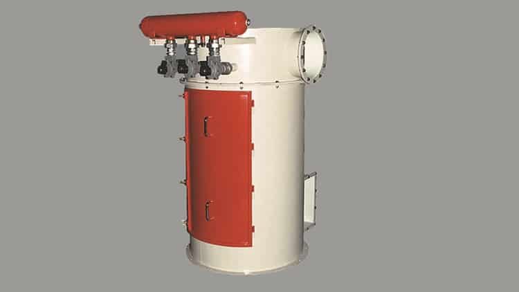
These dust and particulate material collection systems should not only eliminate pollution sources but also help improve process efficiency through product recovery.
How is an industrial aspiration system determined and sized?
1.a – Centralized industrial dust collectors
1.b – Compact or insertable industrial dust collectors
Once the typology is determined, the involved elements must be sized, with the most important being the air-to-dust separator. For this separation, bag filters or air cyclones can be used.
Its determination has two stages:
2 – Calculation of the air filter or cyclone and fan size
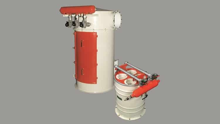
3a – HDFA Filter: Designed to optimize dust separation with the addition of the cyclonic effect of air intake.
3b – HDFQ Filter: Its design allows for space-saving and cost reduction. Additionally, they allow for larger filtering surfaces.
3c – HDFT Filter: Small and specially developed for low airflows, such as in hoppers where pneumatic conveyors discharge.
3d – Cyclonic separators models CA and CONICEL: The former has a cylindrical upper separation part, while CONICEL cyclones have a conical-shaped body. It should be noted that cyclones have a lower percentage of dust separation compared to bag filters.
If you’re interested in learning how a bag filter works and why it’s more or less efficient, follow the next link.
1 - Main typologies of industrial aspiration systems
In the following diagrams, the two most common aspiration typologies with examples of them can be seen.
In all of them, the four main components present in any industrial aspiration installation are distinguished: (We exemplify the diagrams with filters, but these could be replaced by cyclones.)
1 – Capturing device: Typically hoods or hoppers through which contaminants are captured. It must have the appropriate geometry to allow the dust to be dragged away.
2 – Aspiration ducts or pipes: Responsible for carrying air loaded with the contaminant at the appropriate speed to the chosen filter or separator, and then to the fan.
3 – Purifying or separating equipment: It receives the dust along with the air and separates it. The most common ones are cyclonic separators, bag filters, dust collectors, etc.
4 – Air generator or blower: Generally, centrifugal fans provide the necessary energy for the dust-laden air to flow through hoods, ducts, and the separator, ensuring the necessary flow and pressure to overcome the system’s resistance (system pressure loss).
1.a - Centralized industrial dust collectors
This is an aspiration system that aims to capture the contaminant as close as possible to where it has been generated, in one or more sources, and conduct it to the collector device.


05- RHS debarker
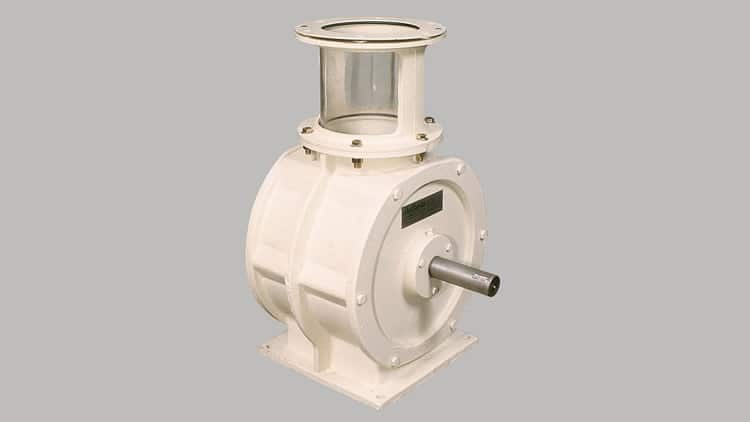
06- Outlet rotary valve
07- Conical sieve CC
08- Level control
09- FL fluidizers
10- Butterfly valve
1.b - Compact or insertable industrial dust collectors
Unlike the centralized aspiration system, these are mounted on the control point, and in the same capture place, the dust is aspirated and retained by the purifier, to then be discharged into the device where the contaminant was generated, recovering it for the process.


05- Screw conveyor
06- Inlet rotary valve
07- Dump truck
08- Underground hopper
09- Pneumatic conveying
10- Weigh hopper
11- Butterfly valve
12- Outlet rotary valve
13- FL fluidizers
14- Lobe blower
15- Conical sieve CC
05- Screw conveyor
06- Inlet rotary valve
07- Dump truck
08- Underground hopper
09- Pneumatic conveying
10- Weigh hopper
11- Butterfly valve
12- Outlet rotary valve
13- FL fluidizers
14- Lobe blower
15- Conical sieve CC
2 - Selection and sizing of bag filters and fans
When selecting and sizing equipment, the physical-chemical characteristics of the product, type and characteristics of emission points, contaminant concentration, site and/or installation environment conditions, requirements, and regulations must be considered.
This information allows the designer of aspiration installations to calculate the ideal aspiration flow, the necessary filtering surface, characteristics of the filtering elements, and other system components.
Among the selection or sizing parameters of bag filters, Filtration Velocity, also known as Filtration Ratio, stands out. It is defined as the maximum contaminated air flow in m³/min that can pass through 1 m² of filtering surface. It is established based on the characteristics of the product to be filtered, its granularity, and concentration, filter type, etc.
The filtration ratio for our self-cleaning filters with air pulses ranges from 1 to 6 (m/min). Although there are tables and empirical formulas to approximate the ideal value for each contaminant, an analysis of material samples, background

Vf = Q / Aft and
Aft = π · Ø · H · n
Where:
Vf = Filtration velocity (m/min)
Q = Airflow (m³/min)
Aft = Total filtering area (m²)
Ø = Bag diameter (m)
H = Bag length (m)
n = Number of bags
Another important parameter when sizing a bag filter is Upward Velocity, defined as the air velocity through the open area between the filtering bags inside a dust collector. If this upward air velocity is too high, the dust expelled from the bags during cleaning will not settle in the lower hopper. Instead, it will be re-entrained and carried back to the bag surface, causing pressure drops, excessive compressed air use, and shorter bag life. A typical upper limit for upward velocity is 0.5 to 1.2 m/sec and should always be lower than the product’s floatation velocity in the air.
Vi = Q / (At-Am) and
At = A · L
Am = (π · Ø² · n) / 4
Where:
Vi = Upward velocity (m/sec)
Q = Airflow (m³/sec)
At = Filter cross-sectional area (m²)
Am = Bag cross-sectional area (m²)
A and L = Filter sides (m)
Ø = Bag diameter (m)
n = Number of bags
Cyclone separator calculation:
Unlike bag filters, cyclones separate the product from the air by centrifugation. Thus, heavy particles (dust) adhere to the cyclone’s cylinder, while the lighter ones (air) remain in the center and exit through the top.
To determine the appropriate cyclone, the required airflow is also considered, and depending on the desired separation efficiency, the pressure loss or accepted pressure drop is determined, which dictates the cyclone’s diameter. In many cases, cyclones are placed in series to improve efficiency.
The main advantages of cyclones compared to bag filters are:
- Lower cost
- Less maintenance
- Higher hygiene
- Less noise
The disadvantage is lower efficiency, as the dust separation percentages are lower.
3-Types of bag or cartridge air filters we can supply
We manufacture various types of bag filters, all with pulse-jet self-cleaning, in steel or stainless steel.
Bag or cartridge filters: The standard diameter is 120 mm.
- The bags are made of punched polyester mounted inside galvanized baskets.
- The cartridges are also made of pleated nonwoven fabrics and have a larger filtering surface.
Possible accessories:
Bag dirt measurement: With the addition of manometers that measure the pressure drop across the bags or cartridge filters, saturation can be automatically controlled.
Explosion protection: No conductive elements are inside the filter. Explosion vents can optionally be added.
Discharge hopper fluidizers: To prevent product clogging in the filter discharge, fluidizers can be added to avoid it.
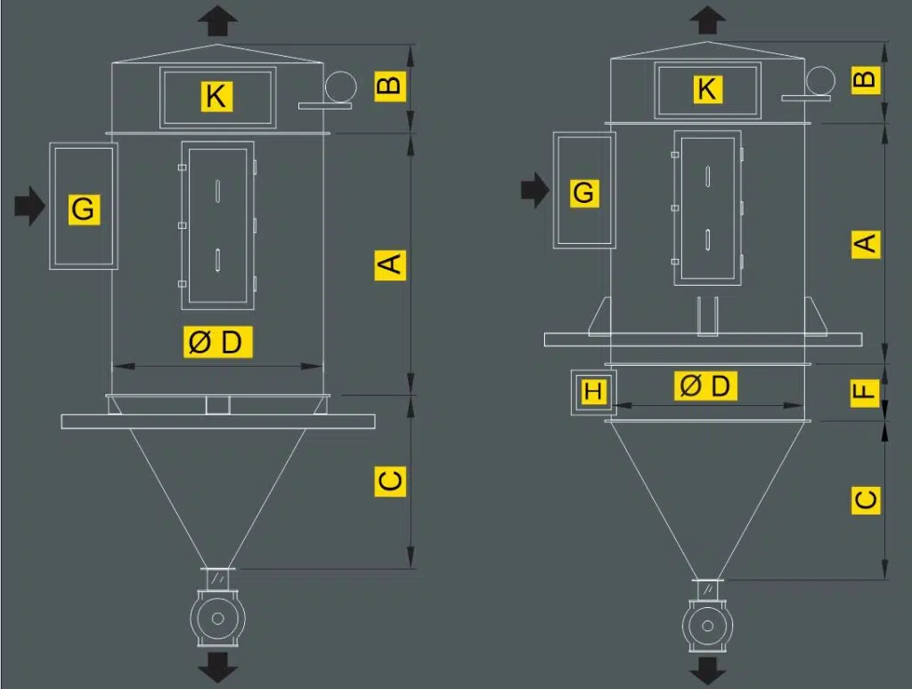
3.a - HDFA Round Section Bag or Cartridge Filters
HDFA filters are designed to achieve optimal dust separation by adding the effect of cyclonic separation. Cleaning solenoid valve 1½” G.
3.b - HDFQ Square Section Bag or Cartridge Filters
HDFQ filters are designed to save space and reduce cost. They come in two size groups: from 8 to 16 bags with side door access and from 40 to 160 bags with top head access. Filters up to 16 bags have a 1″ G cleaning solenoid valve, and the rest have a 1½” G valve.
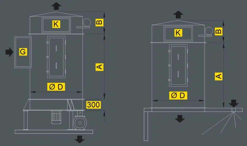
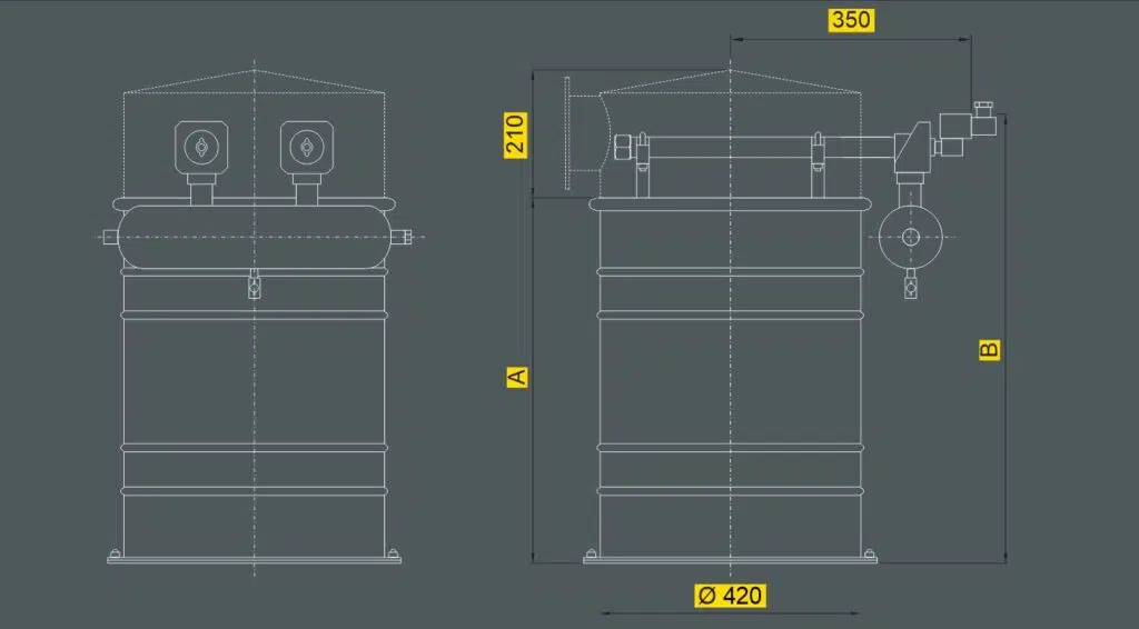
3.c - Small HDFT Bag or Cartridge Filters
HDFT filters are small and specially developed for small airflows, such as in hoppers where pneumatic conveyors discharge.
Bag Filters: How They Work and Types
Among the purifying or separating equipment used in localized aspiration systems, bag filters are the most widespread and representative of solid separation in a gas flow. They have technical textile filtering elements inside.
Cloth filters separate particles by obstruction, impact, interception, diffusion, and electrostatic attraction. The fabric is made of fibrous materials, natural or synthetic, which can be woven or non-woven (felts). Advances in non-woven textile production (punched fabrics) in recent decades have made them predominant due to their improved mechanical, chemical, and high-temperature resistance.

Needlepunched cloths are identified by their thickness and weight per unit area. The fabric or filter media is porous, and therefore allows air to circulate through it, retaining particles on its “dirty” side. Another parameter that identifies the textile is its permeability, which is defined as the volume of air that passes through a surface in a unit of time with a given pressure difference. The combination of both parameters determines the retention efficiency of the filter cloth.
The needlepunched fabrics used in filtration have a mesh that provides mechanical resistance to the textile. On the other hand, manufacturers apply a treatment on the side that will be in contact with the dust (generally flamed), thus presenting a smooth surface that will facilitate the detachment of the material retained on the surface. The maximum retention efficiency is obtained progressively, until the smallest particles that are retained generate the so-called “filter cake”. For this reason, in some cases, the so-called “preloading” is performed, which achieves the necessary filtering capacity by introducing into the circuit inert material of controlled granulometry that generates this cake.

A: Electrostatics
B: Diffusion
C: Gravity
E: Inertia
F: Impact
G: Gas flow
H: Felt
I: Clean air
J: Backing fabric
K: Filter cake
L: Fiber
Bag Filters: How They Work and Types
Due to cumulative material impregnation, bag filters have systems that help dislodge retained dust, called cleaning or self-cleaning systems. Our filters primarily use the pulse-jet air reverse cleaning system. This significantly reduces the filter size while increasing its efficiency.
Self-cleaning system components:

A – Diaphragm valve
B – Blower pipe
C – Venturi
D – Bag
E – Compressed air tank
- Compressed air buffer tank.
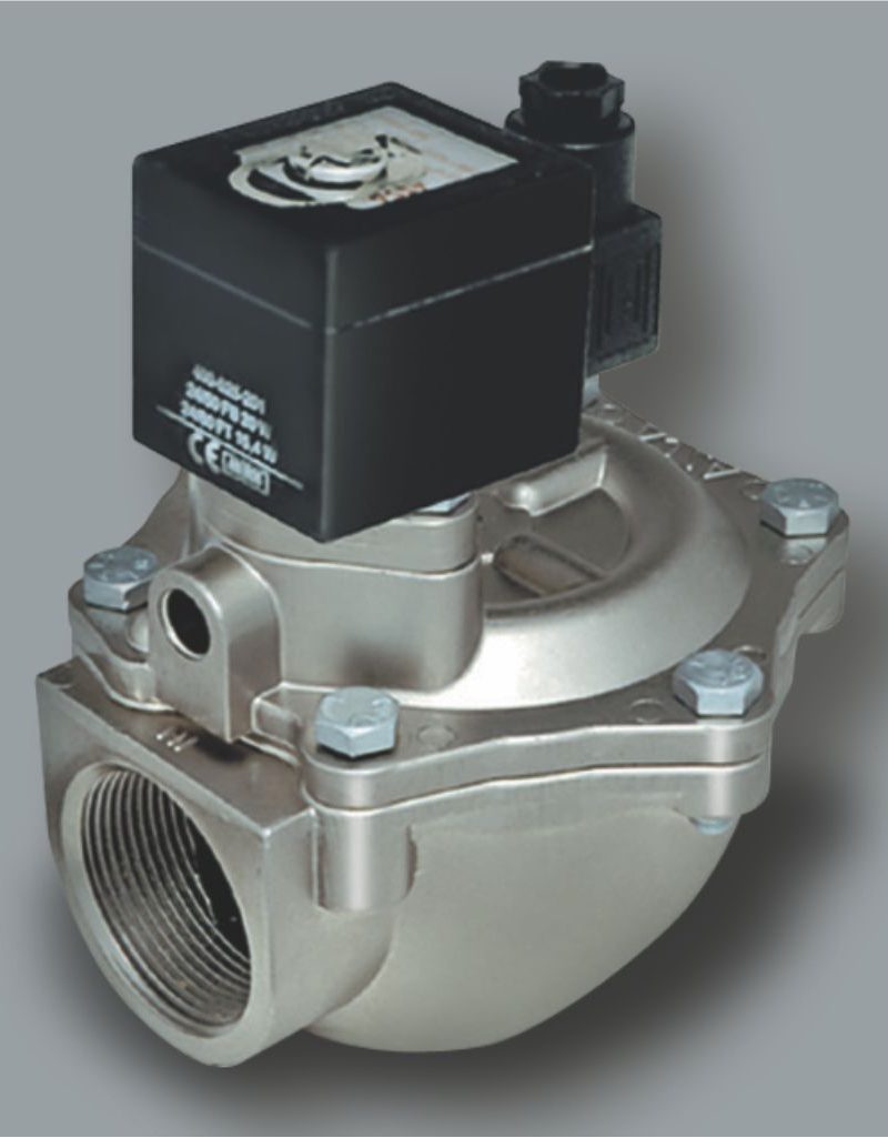
- Diaphragm valves with pneumatic or electric pilot, in charge of achieving the air pulses or shots for cleaning.
- Pipes or blowing flutes, in charge of introducing the compressed air pulses inside each sleeve.
- Accessories of conduction and connection of the compressed air circuit.
- Accelerator or Venturi tubes (many times they are part of the sleeve holder baskets).
- Programmable electronic sequencer, in charge of managing the sequence and duration of the cleaning cycles. Often associated or including a differential pressure gauge that enables the enabling of the cleaning cycles according to demand, within a range of previously set pressures.

Principle of operation of self-cleaning:
Inside the main body, the bags or cartridges are mounted vertically. The dust-laden air flows from the outside of the bags through the filter fabric. The clean air rises through the interior of the bag to the fan or simply to the outside.
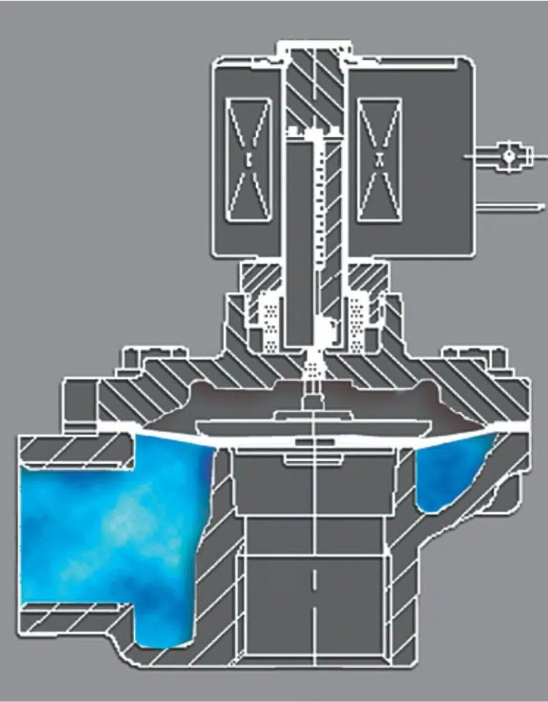
At regular intervals and one group after another, the filter bags are cleaned by solenoid valves and nozzles that inject the air produced by the former. The cleaning process consists of rapid high-flow pressure air pulses in reverse flow, lasting approximately 0.2 seconds each. With each of these blasts, the bags inflate abruptly, causing the dust that was stuck to their outer surface to dislodge.
This cleaning does not interrupt the suction. The pulse is transmitted to a line of bags (generally no more than 14 bags per row) and the usual frequency is in the order of 30 – 120 seconds between blasts. These firing cycles can be uninterrupted or as needed if a pressure switch monitors the saturation state of the filter fabric.
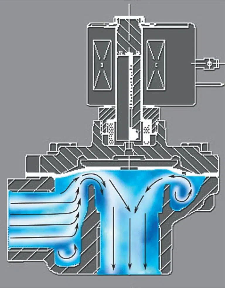
Cleaning solenoid valves: Specifically developed for bag filters. They produce a rapid high-flow instant air pulse, achieving very efficient cleaning. They are controlled by a programmer.
Products we typically handle in our air suction and filtration installations:
- Wheat
- Maize
- Oats
- Coffee
- Cocoa
- Rye
- Beat
- Rice
- Girassol
- Chickpeas
- Soybeans
- Peanuts
- Peanuts
- Spices
- Balanced feed
- Pellets or feeds
- Crystalline sugar
- Impalpable sugar
- Cocoa
- Coffee
- Coriander
- Curcuma
- Gelatin
- Bone meal
- Fish flour
- Milk powder
- Dried beans
- Bread crumbs
- Batter
- Aluminum powder
- Atrazine
- Bentonite
- Borax powder
- Lime
- Caolin
- Activated carbon
- Calcium carbonate
- Cement
- Shell
- Quartz
- Titanium Dioxide
- Dolomite
- Fertilizers
- Monoammonium Phosphate
- Diammonium Phosphate
- Tricalcium Phosphate
- Mica
- Refractory Materials
- Sodium naphthalenesulfonate
- Pigments
- Soaps
- Salt
- Precipitated silica
- Caustic soda
- Magnesium sulfate
- Zinc sulfate
- Tanine
- Diatomaceous Earth
- Dyes
- Gypsum
- Lithium
- Afrecho and afrechillo
- Wheat semolina and semolina
- Semolina
- Rebasillo
- Zootechnical flour
- Maize semolina
- Semolina
- Polenta
- Wheat flour, corn flour, soy flour, etc.
- Germ
- Starch
- Hull
- Polycarbonate
- Vinyl polyvinyl chloride or PVC
- Polystyrene or PET
- Polyethylene
- Polypropylene
- Expanded polystyrene (Styrofoam)
- Sawdust
- Wood
- Cork
- Soap poder
- Pigments

